Homebuilt ROV - Beginning Electrical and Controls
Electrical and control system design concept
My first ROV used a very rudimentary system to control the motors and receive video signal through the tether. In addition to a common ground connection through the tether, each motor individually received power through a separate tether connection, controlled by non-proportional switches at the surface. This was necessary due to the ROV having no onboard microcontroller or control computer to handle more complex communication from the surface.
My new design incorporates an onboard microcontroller to reduce the number of required tether connections by using an onboard microcontroller to create a UART (universal asynchronous receiver/transmitter) serial communication connection with a surface controller, allowing complex control commands or telemetry data to pass through the tether in either direction with only two serial wires and a ground connection, which will also be common to the motor power.
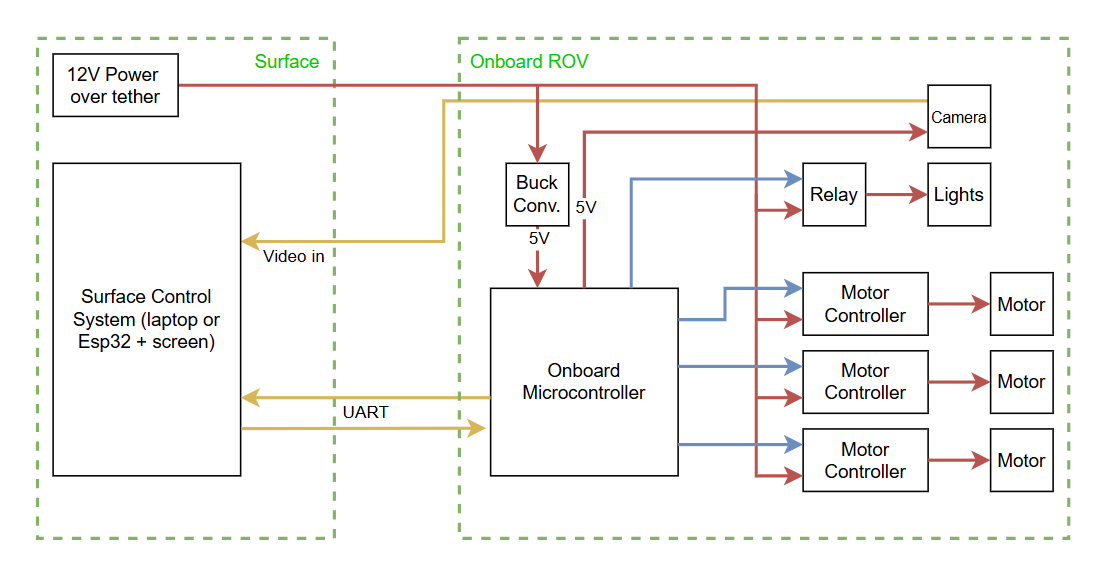
A simple diagram of my current electrical system design. Ground connections connecting all devices are omitted for clarity. Yellow arrows represent data, blue represents control signals (either PWM or digital high/low) and red represents power supply
Simplifying the Tether
As can be seen in the diagram above, the tether connection between the ROV and the surface control system should hopefully be simpler with this configuration. It would be ideal if the video feed could also pass through the UART connection, but further investigation is needed about whether this is possible without introducing more costly equipment. Additionally, further testing of the motors will reveal whether the tether can be reduced to one Cat. 5 cable from the two used in the previous ROV without excessive voltage drop or overheating.
Testing Data Transmission Over the Tether
An early concern of mine was whether control commands or telemetry data could be sent over the tether with a UART connection. My research indicated that the lower the baud rate (data transmission frequency) used, the longer a UART connection could be made. The Cat. 5 cable spool I had used for the previous ROV had a length of around 100 feet. I connected two ESP32 microcontrollers through the tether and found that data could be transmitted well over one strand of the Cat. 5 cable at around 1000 Hz, which by my estimation should be enough for fast enough control inputs.
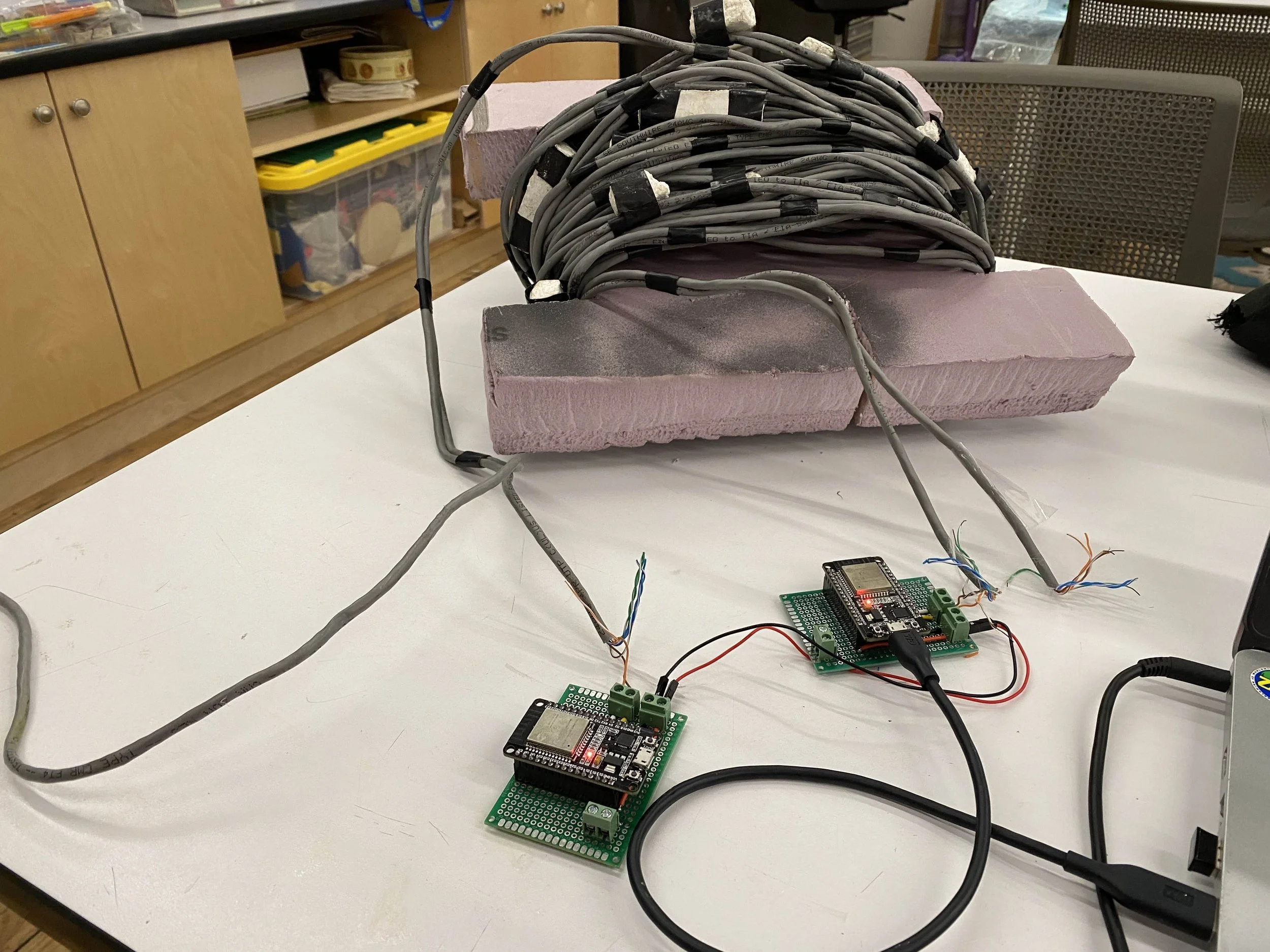
Testing UART connection through the tether
The next stage of the project will involve testing motor controllers and building circuits to connect them to the onboard microcontroller.