Homebuilt ROV - Lessons Learned from Motor Controller Troubleshooting
I hand soldered some circuit boards to connect an ESP32 microcontroller to the three HW-039 DC motor controllers I had selected for this project.
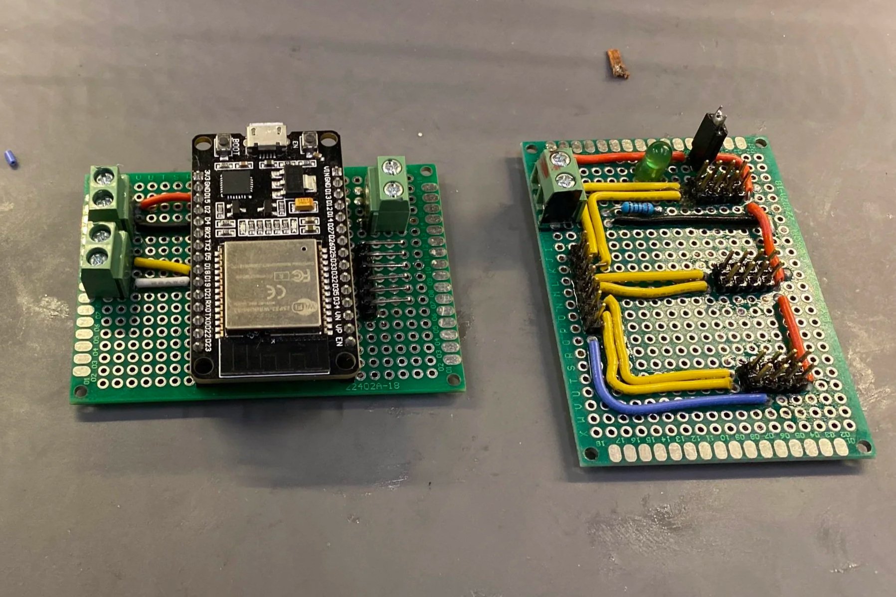
Boards to connect the ESP32 to HW-039 motor controllers
Initial testing
When I built the boards above, I used a multimeter to test continuity in the joints, and to make sure that no shorts were present in the circuit that could disrupt functioning or cause damage. My testing showed my boards to be clear of any unwanted shorts and that all pins appeared to be connected as expected.
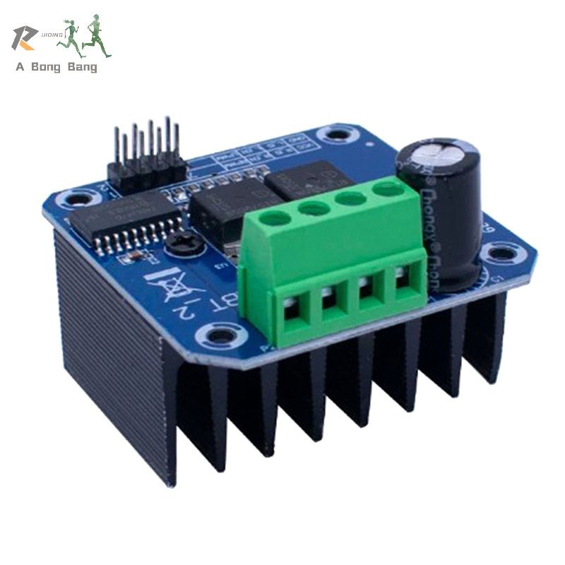
HW-039 Motor Controller
Problems
However, when I plugged in my motor controllers and and supplied power, I could not get the motor controllers to work. They would only rarely power on, and usually refuse to spin the motors at all.
By plugging a motor directly into a 12V power supply, I could confirm that the motors were fully functional. And because of my previous testing, I was relatively sure that my circuit boards were also functional.
Troubleshooting
Initially, I suspected the motor controllers themselves were failing, or that the ESP32 was outputting a PWM signal at the wrong frequency. However, it was unlikely that all my motor controllers had failed simultaneously, and my research indicated that the motor controllers should take the input from the ESP32 PWM.
Eventually, I decided to actually examine the signal that was being outputted to the motor controllers by the ESP32 breakout board I had made. In hindsight, I should have done this much earlier, but my thinking about the issue was clouded by my preconceived thoughts that the problem came from the motor controllers themselves.
The ESP32 outputs 3.3 volts through its GPIO pins, while HW-039 motor controller will accept PWM control inputs at anywhere from 3.3 to 5 volts. When I used an oscilloscope to probe what the ESP32 circuit board was outputting to the motor controller however, the PWM signal read only just over 2 volts at the output from the custom circuit board, and the proper 3.3 volts directly from the ESP32 pin. Somehow my handmade board was dropping the voltage to a level below what the motor driver could take as input, despite continuity testing appearing completely normal.
While I am unable to examine the cause in detail, my best suspicion is that excessive heat during soldering had caused damage to the perfboard material, causing conductivity, perhaps by melting the copper or from solder leaking between layers of fiberglass.
The eventual simplicity of the problem in light of the amount of time I had spent chasing red herrings has made me reflect on a few lessons I have taken away from this incident to keep in mind during future work.
Lessons learned:
Don’t be convinced that a manufactured object is free from error based on passing a test that is unable to encompass all aspects of functionality.
Step back and reconsider gaps in data or understanding when seemingly clear solutions fail to solve the problem.
Thoroughly test all relevant aspects of a newly manufactured part, especially in the case of handmade parts. For example, not only testing for continuity and shorts, but testing for any potential current flow between pins in this device would have identified the problem.
Custom designed printed circuit boards are on order at the tine of writing, hopefully reducing the chance of build quality issues for this project in the future.